
Reflection on the Gyro sensor scoop challenge Circuit Diagram This is a relatively simple, visually effective balancing robot project that only requires four components to make. Detailed video, instructions, schematic, and code at: 40 // supply your own gyro offsets here, scaled for min sensitivity 41 mpu. setXGyroOffset (-479); 42 mpu. setYGyroOffset

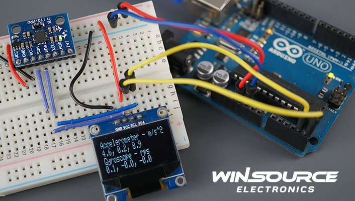
code. Make sure you have the wire.h library installed. It is used for communication between the Arduino and the Gyroscope Module. The robot's movements are controlled through the if else statements in the code. In short the Gyroscope gives it's tilt values to the arduino. Then these values are used by the arduino to move the robot.

Diy Gyroscope Controlled Robot Using Arduino (In 4 Steps) Circuit Diagram
Arduino Uno you can also use Arduio nano too, but some changes in connections and codes need to be made. Piece of cardboard,I will be using 27cm*8cm rectangular piece. Dual shaft Gear Motor some call it as BO Motor and L298N Motor driver. Gyroscope + Accelerometer module I am using MPU-6050. Hot glue , Jumper wires and other small supporting
In Step 2, we discussed the importance of reducing lag to maintain gyroscope's accuracy. When modifying the Arduino code, avoid using delay() and Serial.print(). The serial monitor and its printing functions use USART serial communication. Arduino sends data to the serial monitor on the computer via the HC-05 wireless communication.
Gyroscope Robotics: Revolutionizing the Future of Automation Circuit Diagram
It is best to position it at the center of the robot, between the two wheels. The sensor will be responsible for detecting the robot's tilt and providing feedback to the Arduino. Step 4: Connect the Gyro Sensor Connect the gyro sensor to the Arduino board using jumper wires. Typically, the MPU6050 has four pins: VCC, GND, SDA, and SCL. This experiment demonstrates how to use a gyroscope to stabilize a system, such as a robotic arm or drone, with the help of an Arduino. Components Needed. Gyroscope (e.g., MPU6050) Arduino; Motor (for stabilization) Jumper Wires; Circuit Setup. Connect the VCC and GND of the gyroscope to the 5V and GND pins on the Arduino.
