
Charging and discharging of a capacitor model Circuit Diagram In this topic, you study Charging a Capacitor - Derivation, Diagram, Formula & Theory. Consider a circuit consisting of an uncharged capacitor of capacitance C farads and a resistor of R ohms connected in series as shown in Fig. 3.14. 2- My design uses a transformer, instead of an inductor. This avoids overvoltages, if you run Uzzors2k's circuit without a capacitor load the chances are the circuit gets damaged. The low inductance of the primary helps to reduce voltage peaks, if the capacitors suddenly disconnected the circuit should still work afterwards. To charge a capacitor, you need a circuit diagram that shows how to connect the components to the capacitor in the correct order. This type of circuit diagram might include the capacitor, a supply voltage, and a resistor.

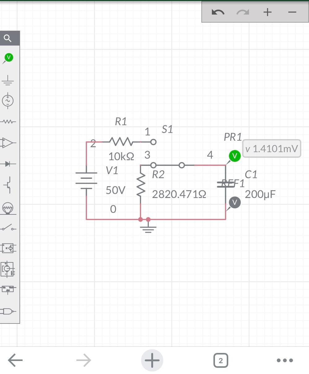
Looking for a way to charge a capacitor? If so, then your simplest solution to do it is the RC circuit. We will also find the capacitor charging equation. This type of circuit is quite simple. Connecting the resistor, capacitor, and voltage source in series will be able to charge the capacitor (C) through the resistor (R).
Derivation, Diagram, Formula & Theory Circuit Diagram
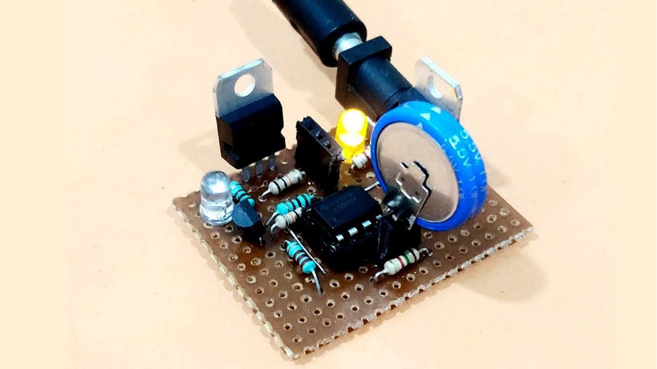
This video is a tutorial for making capacitor charging and discharging circuit. In this hands-on electronics experiment, you will build capacitor charging and discharging circuits and learn how to calculate the RC time constant of resistor-capacitor circuits.
Calculate capacitor charging time easily with simple formulas, understanding capacitor voltage, current, and resistance to optimize circuit design and fast charging applications, ensuring efficient energy storage and power supply systems.
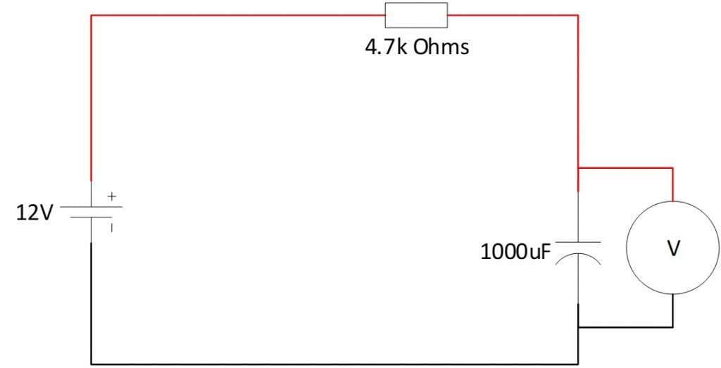
Circuit Diagram For Charging A Capacitor
A capacitor charger circuit is used to ensure that a capacitor is charged safely and efficiently. At the center of a capacitor charger circuit diagram is the transistor, which acts as the switch that completes the circuit and sends current to the capacitor.
